The First AI-Driven Autonomous Robot for Orbital Welding of Pipelines
AROW® Overview
In the ever-evolving landscape of pipeline construction and maintenance, the AROW® robotic welding system sets a new benchmark for innovation. This next-generation solution, powered by cutting-edge AI technology, transforms the welding process by significantly enhancing efficiency and productivity in the demanding pipeline industry.
AROW® is engineered to enable two robots to work simultaneously on the same pipe head, dramatically reducing operational time and increasing throughput. Its innovative casing structure design not only safeguards the equipment but also simplifies the welding process, making it user-friendly even for operators without extensive professional welding expertise. This combination of features streamlines operations while ensuring exceptional quality and consistency in welds.
The development of AROW® is rooted in extensive field experience, gained through close collaboration with our parent company, Chemo Aharon Ltd., a trusted leader in pipeline contracting.
How it Works
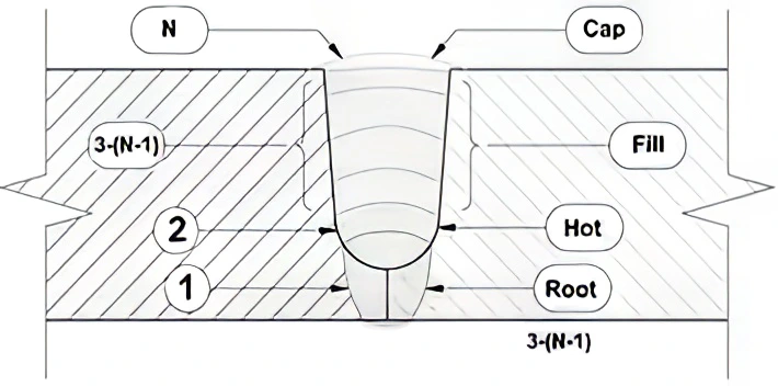
A gas pipeline is constructed from long, thick-walled segments. Before being attached and fitted, the pipes undergo a beveling preparation, typically in a V or U shape.
Multiple welding passes are required, including the root pass, hot pass, filling passes, and cover passes. With AROW, the bevel shape and topography of each pass around the pipe’s perimeter are scanned and measured using a line laser scanner. Simultaneously, welding parameters are calculated based on the robot’s location data, an AI-developed algorithm, and statistically gathered information. The welding torch then moves to the precise position, executing the weld flawlessly with these optimized parameters.
Features and Benefits
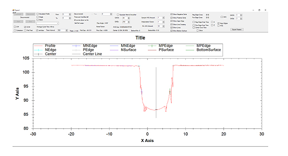
Advanced Laser Sensing Technology
AI-based laser scanning tracks seam grooves in real time, enabling precise data collection and analysis.
Welding Power Source
Uses GMAW (MIG) welding for pipe segments with diameters starting from 12 inches and larger, supporting both uphill and downhill welding.
Servo-Controlled Motion
Features a closed and sealed system housing three servo-controlled motion axes: rotary (θ), horizontal (Y), and vertical (Z), ensuring precise movement and operation.
Automatic Wire Feeder
Equipped with a servo-controlled wire feeder that maintains consistent wire feeding during welding.
Mobility & Positioning
Moves on a toothed ring for accurate tracking and positioning around the pipe.
Operator Interface
Easy installation with a remote control pendant and operator/technician screens, requiring minimal expertise.
Dual Robot Operation
Two robots can work simultaneously on the same pipe for increased efficiency and productivity.
Durability & Reliability
Designed for rugged outdoor environments with high reliability and productivity.
Minimal and easy maintenance required.
Control & Detection Systems
Includes an angle detection system for precise welding and a line laser scanner for enhanced real-time data collection.
Control Cabinet
Contains all essential electrical components and computer systems, ensuring smooth operation.
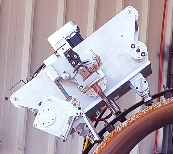
MIG Welding Torch
A MIG welding torch is installed on the robot arm for precise and automated welding execution.
AI Driving New Levels of Precision in Orbital Welding
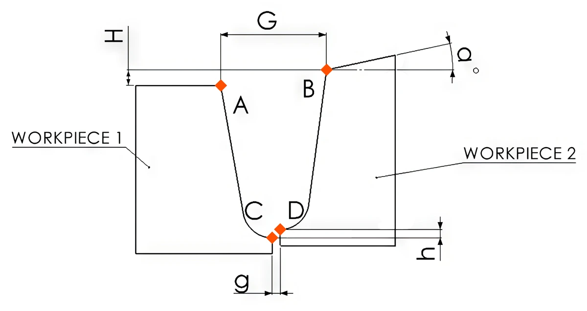
The challenge lies in accurately reading the groove while minimizing the measuring noise, analyzing the data, and filtering out disturbances caused by welding and reflections within the groove. Additionally, it’s crucial to align the laser readings with the position of the welding head. Key points in the groove, outlined below, provide the necessary information to ensure precise welding execution.
Upper High and Low points of the plates connection (A, B).
Bottom High and Low points of the plates connection (C, D).
Upper – High / Low between plates (H).
Lower – High / Low between plates (h).
Upper Gap between plates (seam Gap) (G).
Bottom gap between plates (g).
Robot position angle from the workpiece, workpiece deformation, and Manufacture malfunction. (α)
Veiling glare
Reflections caused by surface grinding
Welding light flashes
Welding drop spatter
Burn Through phenomenon.
Parameters controlled by AI-driven, on-the-fly measuring and optimization:
GMAW Current
Arc length and Arc current
Welding wire speed
Oscillation (Y-Axis)
Oscillation amplitude and frequency
Welding height ( Z-Axis)
Welding speed
AROW Specification
Robot
Pipe Diameter
300 mm (12") and up
Thickness welded pipe
5 – 32 mm (other optional)
Pipe material
Carbon Steel (other optional)
Welding Type
GMAW (MIG)
Ambient temperature
-20 – 55°C
Welding speed
2 – 20 mm/sec (other optional)
Travel speed
2-100 mm/sec (other optional)
Weight
22-25 kg
Dimensions
H-35 cm / W-47 cm / L-45 cm
Tracking system
Laser line tracker
40 mm
Positioning accuracy
+/- 0.2 mm
Grove profile
J & V groves
Welding Torch
Elevation (Z axis)
64 mm
Motion perpendicular to seam (y axis)
64 mm
Welding oscillation
0-4 Hz (parameter setting)
Amplitude – welding oscillation
0-18 mm (parameter setting)
System includes
AROW system
In protective box
Welder Teach pendant
Including
Operator HMI screen
Including
Control cabinet
Including
Toothed band
Including (According to pipe dia.)
GMAW PS
Optional
Gas Mixer
Optional
Working cabinet
Optional (indoor or outdoor)
Welding wire
Wire feeder speed
14 m/min
Welding wire type
Solid / FluxCored
Welding wire size
1-1.2 mm
Power consumption
Operation Voltage
100-240 VAC / 50/60 Hz
Max Power consumption (2 robot system)
750 AV
AROW Comparison table
36" pipe diameter / 19 mm thickness
AROW Welding system
No. Of welding cabin
3
cabins
Cabin #
Cabin 1
Cabin 2
Cabin 3
Welding layer
Root + Hot
F1 + F2 + F3
Strip + Cap
Welding Time
12
20
15
Overall time for pipe section (all cabin works in parallel + overhead * time)
30 -47
min
No. Of welders per day ( 2 per cabin)
6
Welders
No. of sections per day ( 9 hr. shift)
18
Pipe/day
Manual Welding
Professional welder
2
Welders
No. Of sections per day ( 9 hr. shift)
2
Pipe/day
Conclusions & Comparison
Manual Welding
AROW - Autonomous Welding
No. Of welders for the same amount of pipe sections per day
18
6
No of pipe sections per day
2
18
MNP saving
12 professional welders
Increases throughput
~ 900%
Welding expertise
Professional
operators
* overhead Time including: fit-ups, grinding , and transitions between stations
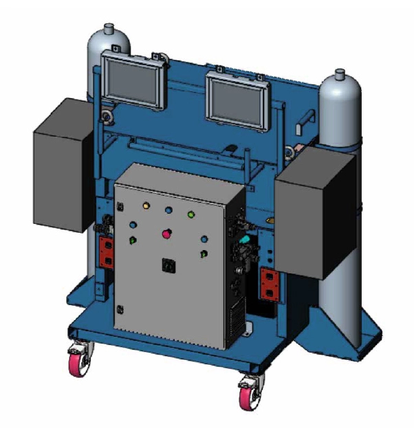
Peripheral Products
AROW Complete Welding Station
Indoor independent welding equipment and control cart
Portable Carriage for indoor welding
Supports 2 AROW systems
Contains : • Welding power supplies • Gas cylinders • Gas mixer • AROW robot control cabinet • Wire feeders • Operator HMI screens
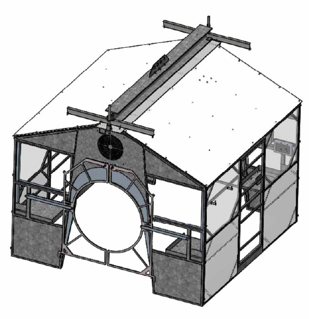
Outdoor Cabin
Designed for outdoor welding.
Modular, removable welding cabin.
Automatic openings for pipes when lifted and closed when on the ground.
Docking station for two AROW robots.
Integrated control cabinets.
Connecting cables to the lifting crawler for efficient mobility.